My Castner Tiegel Project
4/19/04
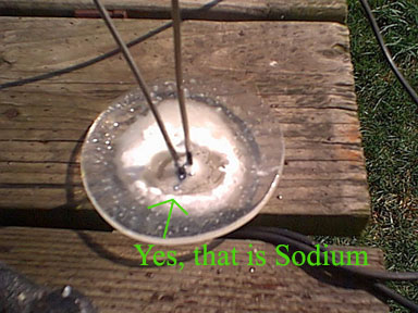
Yesterday I did my proof of concept on making sodium from hydroxide. I got a power supply 4 days ago for charging car batteries, 12 or 6V @ 0 - 15A depending on several conditions. I managed to make some small amount of sodium with it but the amps were low because not much of the electrodes were making it into the melt. Hopefully sodium production will be much faster in the larger setup. Two changes are being considered for the setup:
1) Running it without the steel plate cover. I think that this might just interfere with my ability to see beneath the hydroxide line and once it is on in order to move it I have to remove the bell. What if the level of the hydroxide dips below the bell? Then I have sodium just floating around underneath the plate with no way to get to it, so I probably won't run it with the metal plate on top.
2) The anode is now going to be made of nickel. The design is four prongs interconnected that dip into the melt with roughly the same surface area as the cathode. Seeing how well the nickel anode held up in that most recent run caused me to make this change. Nickel is the only way to go in a castner cell!
4/6/04
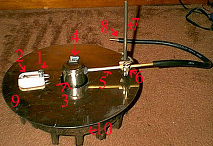
1. Anode, just a stainless steel bolt, might replace with nickel anode but have to grow it from my nickel wire and electrolysis. Or might use copper which is also an anode material but for now just stainless. 2. Allowing me to move the anode up and down it has a clamp on it like those spring weight clamps. This is resting on a ceramic tile to prevent it from completing a circuit with the rest of the cell. 3. Nickel bell that fits into the hole I cut in the metal top. 4. Top of the bell was cut off and re-attached with a hinge to allow for access to sodium being produced. 5. Brass tube leading away from the bell. It leads inside the bell to allow for hydrogen exit and also serves to allow for me to move the bell up and down. 6. 90 degree angle attachment same one used for clamps in a laboratory. Allows me to move the bell up and down and holds it in place. 7. Metal post used to attach the adaptor. Also serves as the hinge for the top to slide it off. Behind it is another hole in the metal leading to another hole in the edge of the pot. A thermometer can be inserted here. 8. Rubber tubing finishes out the exit for the hydrogen. At the end is a brass adapter to allow for the hydrogen to be burnt there or lead into a flame. 9. Stainless top the slides on and off to prevent things from falling into the cell and to prevent CO2 or water vapor especially considering combustion will be taking place right underneath it from entering the cell. Also serves to keep the heat of the electrolyte more constant. 10. Cast iron pot. 14 inches across weighs 24 lbs.
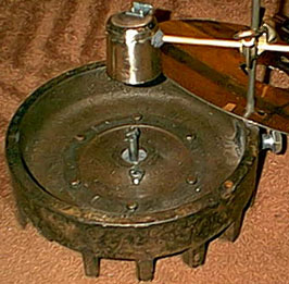
The inside of the pot. That circle of metal on the bottom was what a giant magnet was attached to. I have no clue what this was. In the middle is the cathode, iron this time, from which sodium will be formed and float to the surface and under the bell. The bolts below the cathode and the one to the left are filling holes that were originally in the structure. The cathode is held in place by two things. A circle of wood was cut and tight fit into the hole with the cathode in the middle. On top of that is fireplace mortar. I chose this for two reasons. One is that it is resistant to high temperatures and the other reason being that it is mostly sodium silicate, being that this is the main product of NaOH's reaction with glass I'm assuming that it won't react with the solution much although I'm betting it's soluble in. So I'm hoping that the NaOH forms a solid layer over it being that it is in the middle away from heat. My only remaining stumbling block is the power source. Ideally this cell is run at 7 volts with hundreds of amps. The closer to 7 volts the better the production. So I have my eye on a battery charger with 6 and 12 volt settings that charges at 10 amps, pretty good for a civilian model.
3/24/04
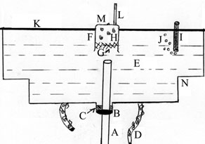
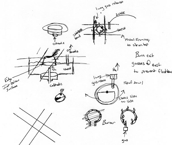
A. Ni Cathode B. Cathode wrapped with teflon tape w/ wood donut underneath for stability C. Sodium Hydroxide poured in molten and allowed to solidify. Re-melting due to convection should be minimal. D. Gas burner to heat apparatus, brass tubing bent into circle w/ holes drilled every inch or so. E. Molten Sodium Hydroxide F. Ni Crucible G. Liquid Sodium Metal H. Hydrogen Gas I. Carbon Anode J. Oxygen Gas K. Metal rods criss cross across the top making a rigid frame to which the anode and the nickel crucible/bell are attached. L. Tube to allow hydrogen gas to exit, may be burned at exit, or piped away to burn further away from the project. M. Section cut from top w/ screw at top to allow it to slide from side to side, see other diagrams. N. The cell is actually contained in a freshly cleaned break drum, much smaller then the diagram would insinuate.